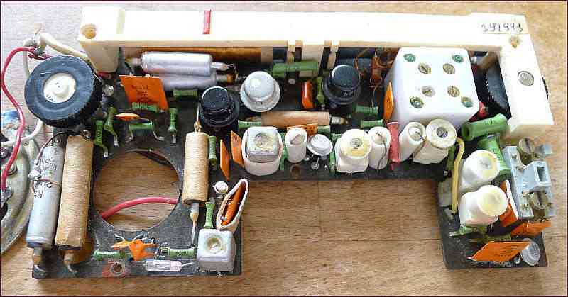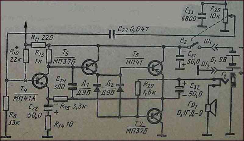
Here is another radio Etiud2 from former USSR with Ge transistors and a simple directly coupled AF amplifier. The impedance of the loudspeaker is more as usual - 60 ohm. The simplicity of the circuit implies different behaviour at different signal strength.

Schematic diagram of the AF amplifier:

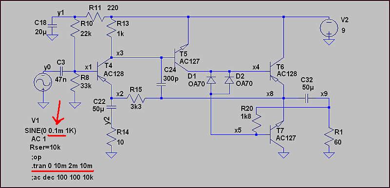
For the LTspice simulation were the original Ge transistors MP37(NPN) and MP41(PNP) replaced with Ge transistors AC127(NPN) and AC128(PNP). Resistors and capacitors were not changed. The speaker with about 0.1mH inductivity has at 1 kHz only 1 ohm inductive resistance, therefore negligible in comparison with 60 ohm real resistance.

I have changed the voltage of 1 kHz input signal to see the output signal distortions and symmetry of limitation.
The red arrow in the circuit diagram shows the input signal strength definition place,
which was changed from 0.1mV to 100mV.
Imput / output signal relation gives us voltage amplification ~100.
Practical audio usage is between about 0.5mW and 50mW output power dissipation corresponding
with 5 to 50 mV of the input signal.
How the output power was computed: Upp/2.8 = Urms; Urms^2/R(60) = P.
0.1 mV / 10mV pp: - without any distortion

0.5 mV / 50mV pp: - light unsymmetry

1 mV / 70mV pp: - stronger unsymmetry

5 mV / 450mV pp - output power dissipation is about 0.5mW: - transient distortion

10 mV / 1.2V pp - output power dissipation is about 3mW: - transient distortion

50 mV / 5V pp: - output power dissipation is about 50mW: - begin of unsymmetrical limitation

100 mV / 7V pp: - unsymmetrical limitation
