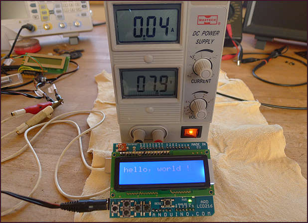
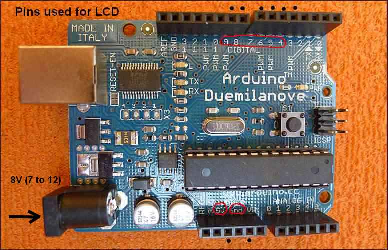
This is the simplest way how to attach a LC display to an Arduino board. 7.9 V from power supply unit, which should be between 7 and 12V is downgraded on the Arduino board to 5V. We have to adjust contrast on V0 pin using the on-board trimmer as a voltage divider. Without properly adjusted voltage could happen, that we see nothing. For testing the display I have used a simple program hello world. You can see it on previous page. The pin names correspond to the pin names on Arduino board - see picture above.
We see on the shield also some buttons, which could be also used for possible
actions. They are connected to analog input pin 0 and the program can identify
which button was pressed, because pressing a button connects input pin 0 to different
voltage values, obtained from a voltage divider, realised on the ARD LCD216 shield.
This way the program recognizes different buttons pressing using only one analog pin.
Voltage on pin0 without signal is 5V. Pressing the buttons from left to right
I have measured on pin0 with a digital multimeter following values:
5.0 4.2 3.3 2.4 1.25 0
Writing, uploading and runing a little program reading pin0 of ADC portc. Pressing
buttons placed on the LCD board gives different voltages.
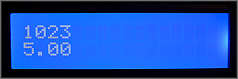
In the first row of the LCD display is the value returned from 10-bit ADC from 0 to 1023.
In the second row of the display is the voltage after a transformation the value from the
interval 0-1023 to the interval 0-5, because the reference is in our case 5V.
The transformation rule is 5/1023 * A0(returned value). 5/1023 is used as the constant Q=004887585.
Pressing the buttons from left to right:
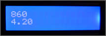
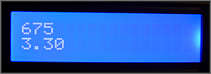
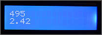
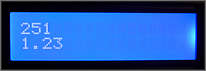
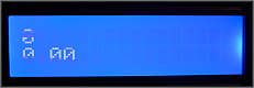
The values are practically same as the values measured with the multimeter.